Fino's ‘58 Wagon

So while waiting on parts I have a couple other projects I am working on...
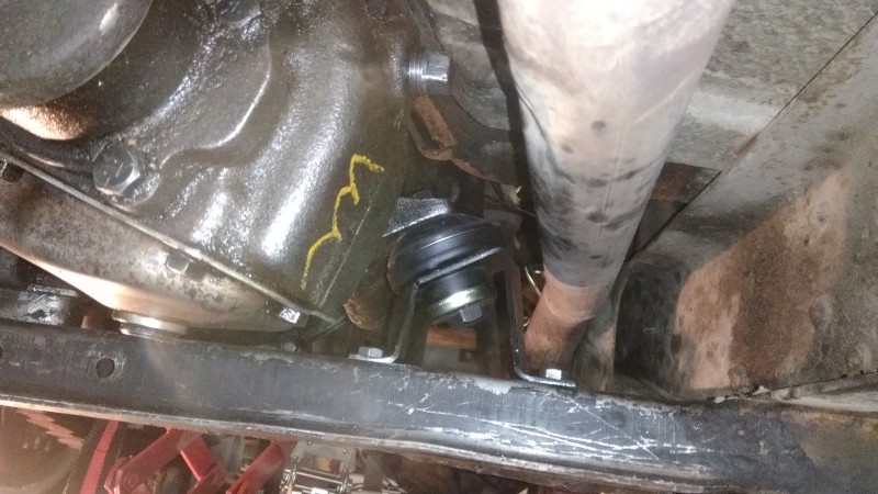
1) getting the radiator reinstalled. One of the issues has been the battery tray, which has been re-located to the right front inner fender as part of the sbc swap, blocks the output radiator hose on that side. The tray is mounted with two bolts to the inner fender, and has a support leg underneath that was welded to the frame that is the problem. Although this pic doesn't quite do it justice, the leg blocks about 1/4 or so of the hose outlet.
P_20200401_171734-1.jpg


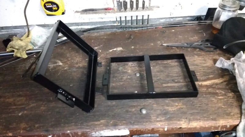
I pulled the battery tray entirely (cut the leg support off the frame), it needed a bit of cleanup and paint, and I also made a top half 'hold-down' that will go with it. Up till now the battery has been classically bungee corded in place. This will be way more solid with some threaded hook rods and wing nuts...I made it using only pieces of scrap I had sitting around so its bit goofy but I avoided C19 infection at the local stores. My welds are not pretty, but they are better than whoever made the bottom tray!...
P_20200419_15065976882a30c6ddaaec.jpg


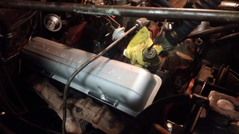
Battery tray back in - modified the base leg support (aka bent it inward) and welded it back to the frame cross-member giving more space for the radiator hose to fit on the radiator outlet...sorry not best pic...
P_20200422_145358.jpg


Also got my fabricated top of battery hold down in place and it seems like its going to work well...fans shroud clears everything nicely...
P_20200422_145412.jpg
 
2nd project is the transmission cross-member...and D18 snubber/torque mount which was rotted out and the bolt was very loose.
While I was under there trying to find the cable clamp on the transmission cross-member - there is so much grease/dirt and gunk that trying to scrape away inches of sticky gunk (and not for the first time) finally broke me down and I decided to pull the cross-member. It has been abused and the front lip was so bent back that it is essentially impossible to access the mounting nuts. So after some creative, determined 'will get this effing thing off' work, I cleaned the 20lbs of oiled dirt off and bent the front edge back enough on the passenger side to allow access to all the mounting holes. Not sure if I am going to work on the other side or not - but the folded back part doesn't cover any mounting holes and the more I bend it the less likely it will go back on easily....This might be a replaced piece if I ever do a full frame off....that sad part is this the better 'after' picture:
P_20200426_162626.jpg


Finally - this allowed me to get to the D18 torque mount and bushing....add a new rubber bushing mount to the parts list...
P_20200426_165859.jpg
 
James, just wondering if the battery tray is mounted to the inner fender as well as supported on the frame? If so you have fixed the body in this corner solidly to the frame with no give at all! This will lead to fatigue cracking of the inner fender at least as the rest of the body is still mounted on rubber and coil mounts. You need to add some rubber mounts between the tray and the inner fender or the leg and the frame.
 
James, just wondering if the battery tray is mounted to the inner fender as well as supported on the frame? If so you have fixed the body in this corner solidly to the frame with no give at all! This will lead to fatigue cracking of the inner fender at least as the rest of the body is still mounted on rubber and coil mounts. You need to add some rubber mounts between the tray and the inner fender or the leg and the frame.

You are 100% correct - and it is a concern. I did add some rubber mounts between the body and battery tray (I'll see if I can get a pic later today - its WFH this morning). I don't love the solution either, but sometimes you gotta take the least bad solution. I couldn't figure out a reasonable way to reinforce the body/fender enough for only a body mount - if the inner fender were not doubly curved, I might have been able to figure out enough of a backing system, but I can't shape metal enough to make it work. I think a full batter tray mount to the frame - kind of like early cjs - could work, but not really doable without removing the fender, and probably a bit of trimming on the inside of the fender to expose the frame rail. I'd like to see how other sbc swaps handled the battery tray....maybe there is an easy solution. As said, its far from ideal, but given that its been this way for 20years, it will work well enough for now...can't fix it all right now. If I keep this thing long term and move towards some bigger projects - like pulling the body to clean up the frame and repaint etc - that would be a good time come up with better solution.

I am not familiar with how the body should space above the frame in the case - my cj has quite a gap between the bottom of the fender and front frame rail....this wagon the fender is basically resting on the front frame rail the entire way. I think the body mount is bent down a bit as well as the body mount bushing/rubber pieces are pretty much deteriorated completely so that is not helping. Anyway, a cracked fender might be annoying, but its not an issue in terms making it driveable for now - besides, I'll probably smash the fender into a rock wheeling it before it cracks.
 
Here are the rubber mounts between the tray and fender....
P_20200427_144954.jpg

I am not really sure they help. I was looking at the set-up a bit more wondering how it hasn't caused damage after 20 years, but I think the reality is the batter tray is basically rigidly mounted to the fender (it moves and vibrates with the fender) and the little 1" wide x 1/8" thick flat bar support leg is in no way rigid, flexes a lot, and allow for lots of movement and vibrations of the tray with the fender. I would guess in the long run, the more likely place for damage is work hardening and cracking near the weld at the frame - I think that is where the difference in movement is occurring. But the rubber mounts can't hurt and maybe will help prolong the life of something....
 
Last edited:
If all the support you have under the tray going to the frame is a 1 x 1/8 flat bar and the two supports on the fender....with nothing under the fender going to the frame but the flat bar, I don't see how the tray is holding horizontal with the battery weight! I would remove the flat bar and replace it with a piece of 2x2 square tubing welded to the frame and the bottom of the battery tray with a gusset off the tubing running as close to the edge of the fender as possible (toward the two fender supports). 2X2 or 1.5 x1.5 angle could be welded to make the square tubing. Maybe I am not seeing what you have but I don't see how it could support the weight of the battery. Flat bar will bend and is not made for support weight pushing toward the center. It does better supporting a hanging weight.
 
Maybe I am not seeing what you have but I don't see how it could support the weight of the battery. Flat bar will bend and is not made for support weight pushing toward the center. It does better supporting a hanging weight.

No, I think you have the right idea, and I don't think the flat bar is actually doing much....the tray is pretty much mounted and supported by the fender and the flat bar just helps stabilize its tendency to hinge. Both when I cut it, and then when I welded it back in, in static scenario without battery load, the bar is under tension (when cut, it popped upward, and when I welded it, I had to push the flat stock down to reach the cross-member and weld it. It actually pulling against (and distorting) the fender (which makes me nervous), but it also helps kind of stabilize it. As said, I'd like to make a single mount to either body or frame, but I don't I can do that as is....its not ideal, but it'll work for now.
 
Two box or angle iron supports coming off the frame at each end of the tray base would be better and then just the fender to add sideways support. Remember you must have a rubber mount each side of the fender to get proper isolation.
 
Got the D18 torque mount installed...I had removed the cross member to get it out and cleanup, so its always fun getting a bent up cross member back in.
P_20200430_165257.jpg


Now on to finishing the e-brake. Made a bracket to hold the lower e-brake cable and welded it to the frame - tried to mimic the one that is still on the driver side. I am going sans wood blocks - hopefully that is not an issue. Eventually the low hanging, obnoxious glass packs will be removed to create even more clearance.
P_20200502_212240.jpg

P_20200502_212348.jpg


Had some issues getting the right upper cable for the T-handle - but its all in and ready to go...but no pics as i got distracted with something else on it. I've been chasing a bad oil leak since I got this thing...it comes from somewhere along the back of the engine, and with the firewall squeezed up so tight its hard to see whats back there. Anyway, I took it for a quick brake test drive around the block and when I got back there was oil dripping out everywhere along the back of the engine and bellhousing...
I've struggled with the oil filter canister and cartridge filter adapter gaskets....The RMS is certainly an option, and also noted the valve covers were leaking a lot (basically everything leaks a lot!). Removing the covers, the cork gaskets were dry and cracked....I think this is the one that was most responsible for the biggest leak, but other areas are certainly seeping:
This is where I think the worst of the leak was coming from - back driver side corner of the driverside valve cover:

P_20200503_175546.jpg


the valve cover that goes in that corner - a few other cracks as well...
P_20200503_175214.jpg


After some go arounds with the VCs, I did what I thought was a darn nice job getting the VCs flat and smooth along the gasket surface and I ended up with some Permatex high tack (the red brush on stuff that I like in the can) on the VCs and fit the gaskets in there nicely and let them set-up for a while so they would be nicely attached to the VC when I went to install. Then I added a thin smear of RTV along the head side of the gasket and installed - in case you ever think about running a fuel inlet line to the carb directly over your VC - don't do it! Its a complete hassle - but was the POs doing not mine. I also think I would put in studs next time first and not have to deal with installing the hardware while holding everything in place. I also ended using long hold-downs - they do seem like they will work way better than the oem style triangular ones I used first (which might now make there way on the cj).
P_20200506_205206.jpg


But nope....didn't work.
index.php
...The VCs are better, but not sealed, and it looks like a lot of the oil coming from the RMS - and its a complete mess....guess it was fun driving it around for 10min. So I ordered an RMS - glad I did a bit of research as the early sbc283 from 57 uses a different seal than the later (59 and after) more common ones. Originally, it would have been a rope seal, but the standard 2piece rubber/silicone replacement (e.g. fel pro 2900) is too thin....the classic chevy specialty stores have 4 piece replacement kits (standard 2 piece neoprene seal and 2 additional wires to fill up space and press the seal forward)....But found out there is one 2-piece rubber seal that is thicker and a direct fit: Best Gasket 3711x and it isn't cheap nor sold much of anywhere.

So we'll see....after spending some time looking and thinking and letting oil drip on my face - there are 3 main sources of oil leak that I can determine....1) the RMS, 2) the oil filter adapter and 3) back of the valve cover gaskets....and while the VCs are far from perfect, I can't believe they could be responsible for this kind of massive oil leak.....about the only thing I think isn't leaking is the oil pan gasket, but maybe it is in the back against the rear bearing cap (its the nice 1-piece reinforced/ribbed silicone one). So we'll (me and my frustrated self) pull the pan and the oil filter adapter and try fixing it again....Supposedly I have a jeep that actually runs and drives and only leaks reasonable amounts of oil - I should probably go find it and drive it.
 
Its been a frustrating couple of months, but may have turned the corner a bit...Had the valve covers and intake manifold off a couple times working on my ability to seal stuff....on my cj, I've never really had much issue with just using felpro gaskets and a bit of RTV or gasket tack, but this sbc seems to leak everywhere, and its hard to get things to seal. This was the rear intake manifold 'end gasket' that I put in last fall - if I would have known then what I know now (and what conventional wisdom says), you don't use the end gaskets on sbc's - just RTV.
P_20200514_130112.jpg


Here was an attempt to seal the VCs - notice the lack of 'imprint' into the bottom of the VC gasket - I did my best to hammer the VC flanges flat etc, but in this case, a thick bead of RTV seemed to be the best way to go - hopefully none of it ended up in the valve train.
The classic spot that leaks between the ram horns:
P_20200519_150046.jpg


The front end of the driver side cover - this is one of the bad leak zones - it comes out when I pour oil into the breather hole you see:
P_20200519_150107.jpg


The rear end of the driver side - another spot creating puddles of oil before...almost no contact all the way around.
P_20200519_150134.jpg


Ended up going with the "Right Stuff" RTV with no gaskets, and that seems to be working better than anything else and while its seeping a bit, it seems to be acceptable for what I need.

While the intake and carb was off, I inspected the carb to see if I could figure out any linkage or mistakes I made during the rebuild - it didn't feel like it was ever opening up the secondaries. Now, I've never driven a quadrajet (or even a 4 barrel carb I don't think), but my gut feeling was that it should be noticeable. First I noticed for what little driving its seen, there was already quite a bit of varnish and gunk building up - especially around the secondary choke plate and butterfly - it was a bit sticky as if it hasn't been operating. When moving the throttle linkage, there are two tabs - as the throttle linkage opens, the upper tab moves down until it pushes on the lower tab. As the lower tab moves, it is connected to linkage that opens the secondary butterfly.
P_20200516_153151.jpg


On the bench. all seemed fine, but when I put it back on the manifold and connected the pedal linkage....The throttle was bottoming out just about the time the upper tab hit the bottom tab - and thus the secondaries were never opening...Here it is with the gas pedal floored - the two tabs just touching, but the bottom tab has not moved.
P_20200516_153208.jpg


I thought I was going to have to figure out some changes to the gas pedal to allow for more travel, but then through some internet research, found that the quadrajet has different mounting locations for the pedal linkage.....In the case of the one I have, it has 3 positions represented by the 3 holes....The pedal linkage was in the middle hole. As the throttle rotates the mounting holes on an arc, the same amount of pedal movement can create different amounts of throttle rotation....So I moved the pedal linkage to the lowest, innermost hole, such that it will cause more rotation.
P_20200516_190110.jpg


Now it allows for the the upper tab to move into the second tab and continue moving to open the secondaries, all with the same pedal range of motion. It will also make the gas pedal a bit more sensitive to subtle changes, but going to give it a try. I even get the return spring out of the uppermost throttle hole and down to its appropriate mounting location on the bottom-most tab and run it towards the firewall.
 
After getting the brakes, leaking oil and tweaking the carb, the overheating was the next issue. Looking back in this thread a couple months, I tried a cheap shroud solution that wasn't enough, and given the arrangement and spacing of the fan in relation to the radiator, I gave up on trying to fabricate a shroud of some type, and decided to go electric fan. As the electric fan pulls close to 20A, that meant redoing some of the electrical and replacing the 30A generator with a 10SI alternator (63A). Started with figuring out how to mount the alternator....Decided to modify the existing homemade bracket that mounted both the PS and generator so I could swap the alternator in for the generator....sorry - there is some hack fabricating here, but gotta learn somehow. Used one of these classic sbc F-brackets to mount on the exhaust manifold as the lower support for the alternator:
s-l225.jpg


Then had to modify the lower portion of the PO's homemade PS bracket...went from looking like this:
P_20200530_140957.jpg


to looking like this:
P_20200530_174754.jpg


Final set-up - using a 3 wire, 63amp 10SI....hopefully that is enough as the fan will pull 18-19A alone, but nothing else other than standard ignition, headlights, heater fan and maybe eventually, electric wiper motor:
P_20200530_175903.jpg
 
Last edited:
Next up was the electric fan - used a 16" SPAL puller fan. Here is test mount using 4 straps around the sides to hold it in place...After finalizing this with proper hardware etc, it is really solid. I was thinking a 5th strap over the top to the flat front panel behind the top of the grille could be helpful with supporting directly against its weight - but it would certainly look a bit shabby (like that matters given my other work on this thing), and honestly, I don't think its needed now.
P_20200606_212016.jpg


Mounted the relay for the electric fan on the inner fender and roughed in the wiring...after testing, if all is good, it'll get cleaned up a bit and taped etc...I am also going to put a junction post on the lower inner fender for +12V that will tie the battery and alternator together and provide a good take off point for high current needs on a relay (such as the fan). Am also putting in a junction post on the inside of the firewall for keyed +12V to switch relays, power the tachometer and eventually a voltmeter and whatever else might be needed. In the short term, keeping the OEM set-up with aftermarket 60A ammeter (from PO) to go with the 60A alternator I just installed.
P_20200611_211341.jpg


For the temperature sending unit for the fan relay - I went with a spacer under the thermostat housing that has 2 threaded ports - used one for the sending unit and plugged the other one. I put just a touch of thread sealant on the first couple threads of the sending unit, but didn't want to use too much and cause any issue with the sending unit not grounding properly.
P_20200611_211100.jpg


As I had to dig around under the dash to find the keyed 12V wire from ignition, I also did some wiring clean-up (got rid of a bunch of jumper slices from the PO that went nowhere or to auxiliary devices since removed) and got some of the speedo cluster working. Got all of the interior dash and auxiliary gauge lights wired to the correct headlight switch terminal so they come on with the parking lights. Replaced some of the bulbs, so the general backlight on the speedo is working, and also got the Amp light wired in and working! (As the 2 wire AMP light socket was missing, I stole the 2-wire oil light socket as I am not using it - separate mechanical oil pressure gauge). I am not using the speedo temp gauge - but both the fuel and temp gauges test like they will work, so at some point I'll have to drop the tank to see what is going on with the fuel sending unit.
P_20200611_213947.jpg


Finally, got the high beam switch and indicator light working.
P_20200612_120605.jpg


When I got it, the headlights came on when the switch was pulled out, but not sure the high beams were coming on or not. I think the lights flickered when the dimmer switch was pushed, but not sure anything was actually changing. Based on how it was wired - I think it was just using a side terminal post as a junction block and connecting the wire from the headlight switch directly to the low beams. The high beam wire was on the center terminal (?) and the dash indicator was on the 3rd terminal and no bulb. I am not all that jeep or wiring savvy, but it doesn't seem that hard to get it right (especially with all the online knowledge available on forums like this).
P_20200612_115553.jpg


Green wire from headlight switch to the center post, wire to low beams to one side post (right in the case), and wire to high beam to the opposite side post along with the dash indicator light to the high beam post. Pretty easy to check the switch functionality with a multi-meter to see which circuits closed when. Headlight relay may be in the future, but one thing at a time for now just to get it back to working - and probably some new wires from the fender junction block to the lights etc.

It was about 90F this afternoon and took it for some city traffic driving - seems to be working - hopefully. The fan definitely run a lots, but if that is what is need to keep it cool, so be it. Its running a 180 thermostat with the SPAL 185 sensor that turns the fan on at 185, and turns it off at 165 - not sure it will ever really turn off as I am not sure it sees 165 anytime other than when its warming up. Hopefully time to drive it a bit and take a break from just working on it....see what brakes next.
 
And somewhere along the line in the last few months, I picked up a set of alloy rims off CL and got some new rubber...I really wanted 16" rims with 235/85/16 tires, but just didn't have the clearance for them with the suspension, and would have settled for 215/85/16 quite readily. After months of looking for used 16" rims (not really oem steel, but anything in the 16x7 range with 5x5.5 pattern), I couldn't justify new rubber and new rims, and I couldn't pass up the deal on these 15x8 alloy rims (4" BS), and got a set of unused, but a few years old Hankook ATs in 30x9.5 cheap off ebay. Not the ideal tall skinny look, but the price was right and will run these until the budget recovers and maybe a new suspension etc is part of the picture. At this point, its more important to get in reliably on the road and being used than making it perfect. Hopefully the rear tires won't catch the fender when flexed too much...The wheels are Superior Industries out of Van Nuys, CA - I have a set of their mag slots on my CJ5. If I ever move to a 16" wheel here, or damage the cj rims beyond repair, I might move these rims to the cj.
P_20200522_175858.jpg
It looks like you are fixing a lot of small items, doing well. About your oil leak at the back of the engine. I chased my SBC motor oil leak back there for several years. New rear seal, pan, intake, valve covers, (just like you). It all helped but not completely. One day while chasing some wiring back there I see a drop of oil fall to the bell housing. Turns out the oil pressure sender for the idiot light was leaking out the end, not the threads. I have a direct gauge also. Anyway no more leaks.
Just one more thing to check. Have fun, enjoy the ride.
 
Factory electric fan setup on my XJ was turning the fans on at 220*F and switching off at 200*F with a factory 195*F thermostat. They are always setup to turn the fans off above that of the thermostat. Usually about 5*F higher. You don't want your engine running colder than the correct thermostat.
You will just wear out your electric fan with it switching off below that of your thermostat. Totally negates the thermostats function too! Higher alternator loads and more parasitic drag causing more fuel to be used as well.

Most people make this mistake thinking that a thermostat is to stop an engine from overheating, hence why they think putting a cooler one will stop it. This is not the case. A thermostat is to stop an engine from running too cold as it increases wear and lowers efficiency. That is why newer engines with better materials and oil etc, are designed to run hotter than older engines.

Once the temperature rises above the thermostats set temperature, it will continue to rise if the radiator can't pull enough heat out for the conditions. It makes no difference whatsoever at point this happens to the final temperature reached. If the amount of heat generated, minus what the radiator can pull from it via heat transfer is say 220*F, then it will still reach that temperature with the thermostat fully open at 160*F or 200*F.

By having the fans turn off lower than the thermostat, you are constantly fighting the thermostat, and actually reducing flow, as it will keep closing to try and raise it back to 180*F in your case.

Sorry for the long-winded explanation, but a lot of people struggle with this.
 
Last edited:
Factory electric fan setup on my XJ was turning the fans on at 220*F and switching off at 200*F with a factory 195*F thermostat. They are always setup to turn the fans off above that of the thermostat. Usually about 5*F higher. You don't want your engine running colder than the correct thermostat.
You will just wear out your electric fan with it switching off below that of your thermostat. Totally negates the thermostats function too! Higher alternator loads and more parasitic drag causing more fuel to be used as well.

Most people make this mistake thinking that a thermostat is to stop an engine from overheating, hence why they think putting a cooler one will stop it. This is not the case. A thermostat is to stop an engine from running too cold as it increases wear and lowers efficiency. That is why newer engines with better materials and oil etc, are designed to run hotter than older engines.

Once the temperature rises above the thermostats set temperature, it will continue to rise if the radiator can't pull enough heat out for the conditions. It makes no difference whatsoever at point this happens to the final temperature reached. If the amount of heat generated, minus what the radiator can pull from it via heat transfer is say 220*F, then it will still reach that temperature with the thermostat fully open at 160*F or 200*F.

By having the fans turn off lower than the thermostat, you are constantly fighting the thermostat, and actually reducing flow, as it will keep closing to try and raise it back to 180*F in your case.

Sorry for the long-winded explanation, but a lot of people struggle with this.

I don't disagree with your assessment at all - that is why I am uncertain how well the current spal 185 sending unit is going to work. But when you talk to the spal representatives, this is the unit they recommend for a 180 thermostat - I am kind of going off their expert recommendation (and its their products). I don't think the fan is ever going to turn off - and if it does, its going to climb right back up to 185 or so and kick right back on. Its $35 dollars or so for the higher temp sending unit (195) so might check that out. there is no higher temp sensing unit that that.
 
Had some unexpected CJ work to do (damaged the front frame horns on the Rubicon - so that repair took priority for a bit)...but back to thinking about the 58 wagon and went down another rabbit hole as this old wagon always seems to do.....some days you love it and some days you wanna sell it....anyway....
I am trying better understand how the sbc engine swap was done in this case. The sbc is in my 58 wagon is from 1957, it does not have the typical SBC mounts on the side of the block. It is mounted using a front 'cradle' mount - Something like this Hurst mount: https://www.speedwaymotors.com/Spee...MIndLu0uzs6wIVEtbACh2-lgseEAQYASABEgKiHPD_BwE
Additionally, I believe the t90J/D18 drivetrain was left in place with this swap. So when a cradle mount like this was used, I believe they just used the OEM 6-226 motor mounts? And did those mounts stay in their original place - or did the mounts get moved?
Another thing I am trying to figure out is what was used to mount the T90 to the sbc. In other words, what kind of bellhousing and mating is there between the sbc and t90 now? Is this the sbc bellhousing with an adapter to the t90? Or was this an aftermarket bell specifically for sbc to t90 adaptions?
IMG_20200915_233535.jpg

IMG_20200915_233638.jpg

IMG_20200915_233552.jpg


thanks - in the long run understanding this current set-up will make it easier to understand and compare some of the sbc swap discussion from Novak where they do the sbc conversion using the T90 with an adapter that keeps the rest of the drivetrain in place, but it also appears to have significantly more firewall clearance than mine currently has.
 
Back
Top