GrandWillys Project

Sorry about going into so much detail on these locks, but I struggled to find much about this on the net so thought others might need the information one day.


Willys1249.jpg

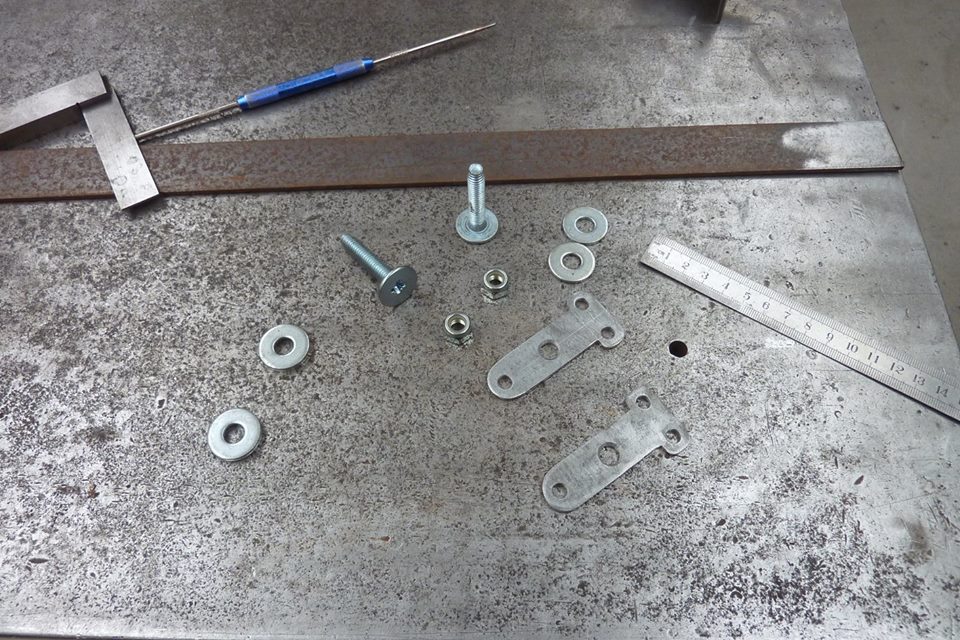
Next up is making the doors lock and unlock. I wanted a manual release on the inside of the door in case something happened to the central locking. I had these wide flat head bolts to use as pivots from an old CRT monitor I think. I always strip down and take fasteners out of everything that is to be thrown out and everything goes into the sorted bins I have. The pivot links were cut from some flat stock.


Willys1250.jpg

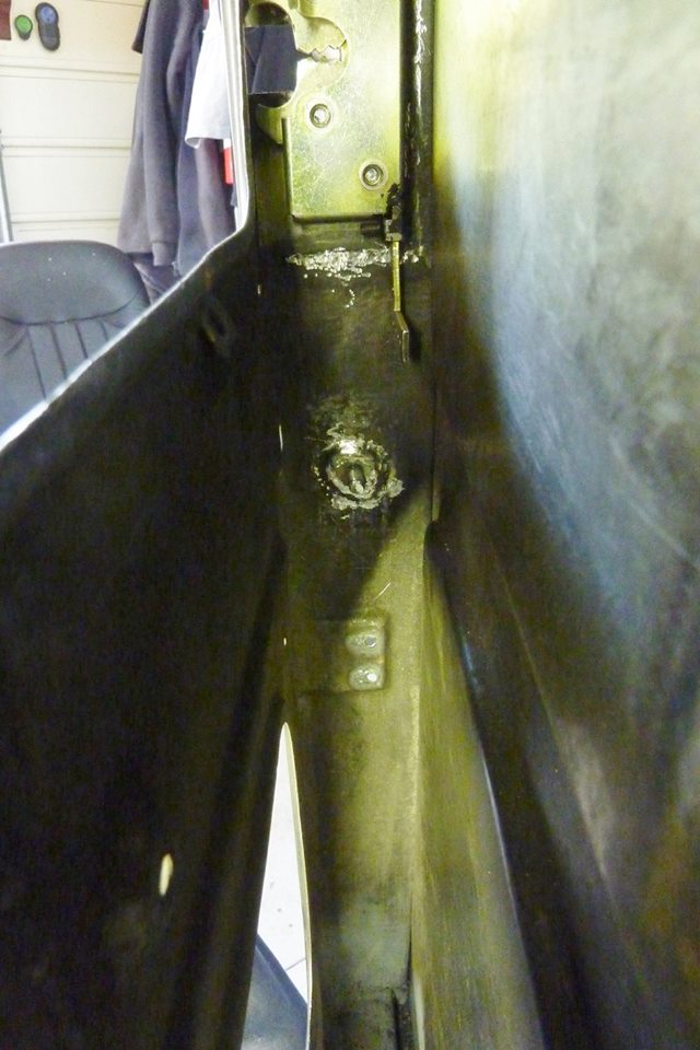
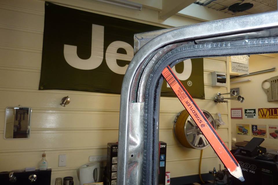
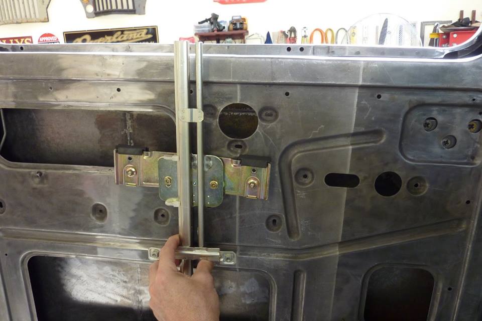
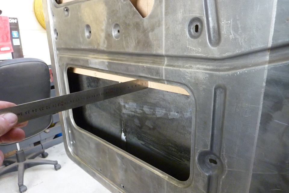
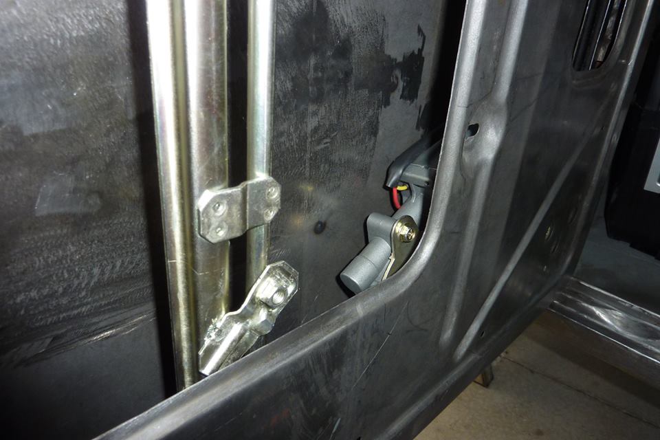
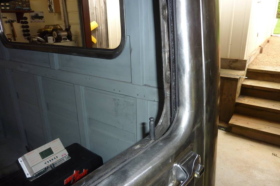
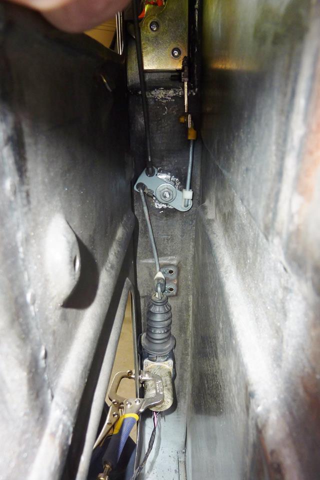
I fully welded the head of the bolt to the door frame. I didn't want any long term fatigue so why I chose the widest flat bolt/screw head to use. What needs to be operated is the L shaped lever coming out of the lock and needs to go straight up and down, but is on the wrong side of the glass.


Willys1251.jpg

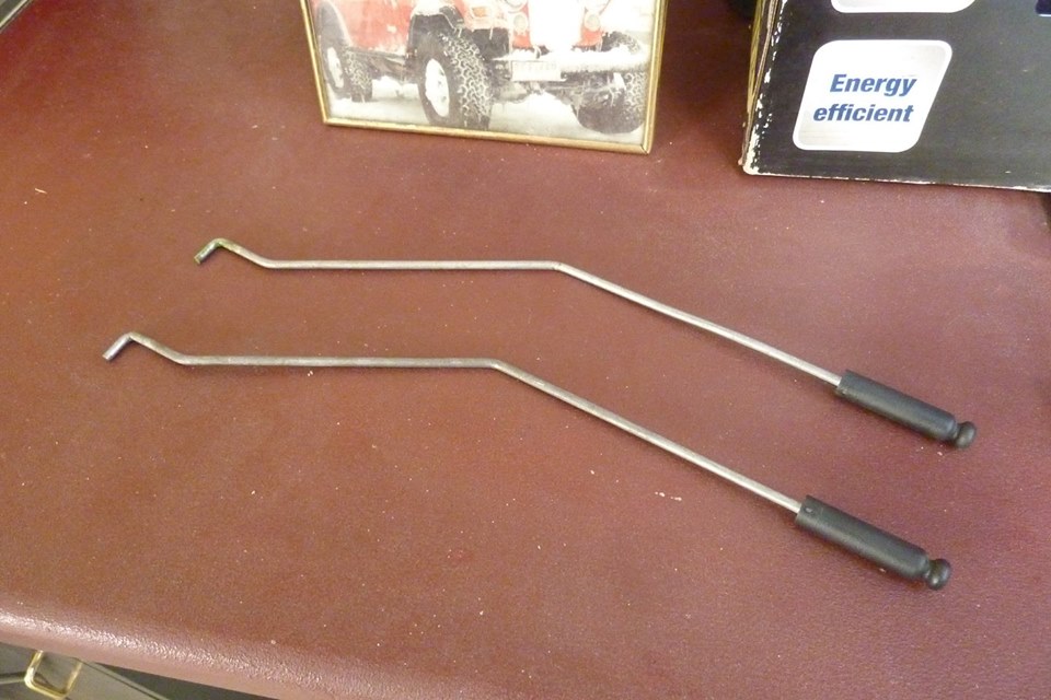
I used these door lock release rods from the donor front doors and bent them to suit the offset I needed.


Willys1252.jpg

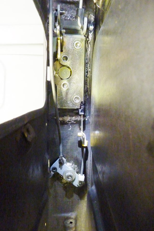
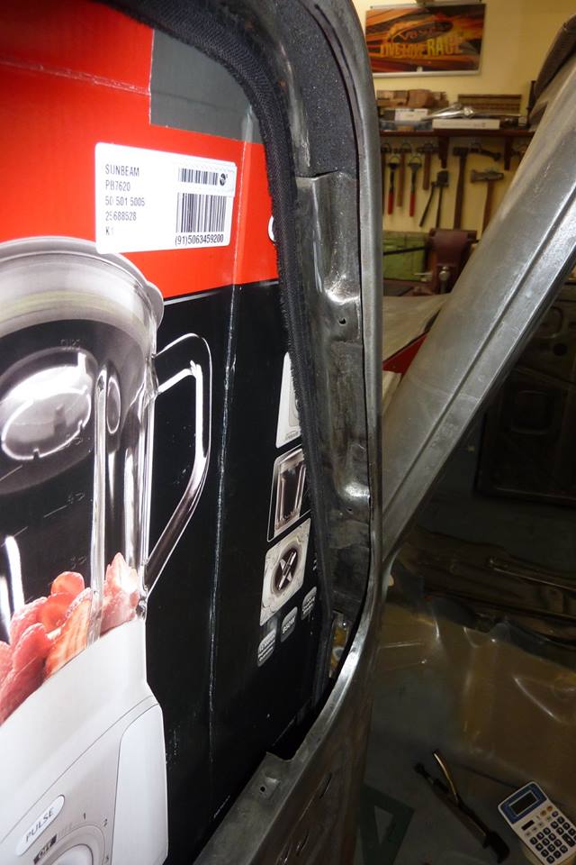
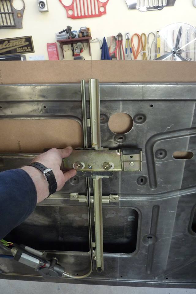
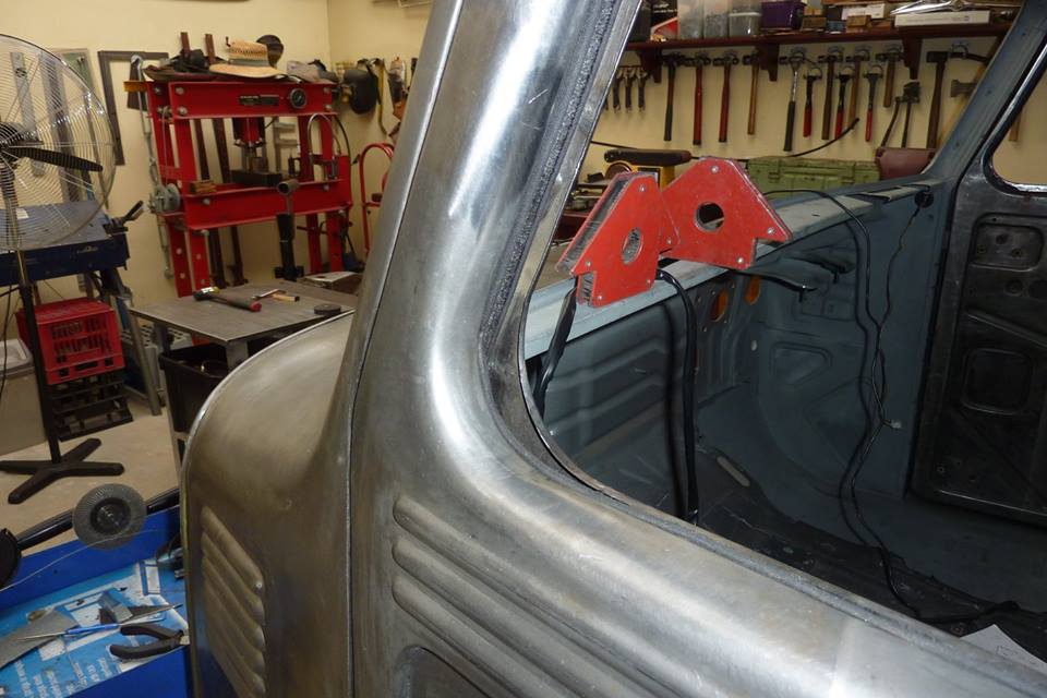
This is the best way I could think of to move the lever up and down directly under it. It sometimes would jam if you tried pushing up on an angle. This is another reason I ran the latch with the locking lever at the bottom as it would work conventionally. Pulling up on the door release knob would pull down the lever and unlock it like shown.


Willys1253.jpg

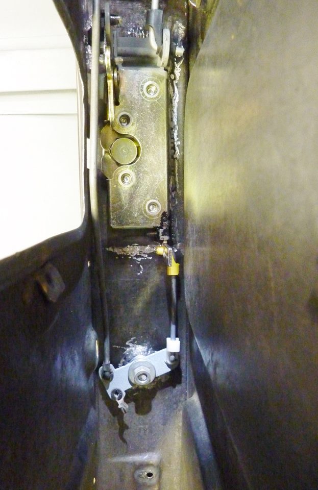
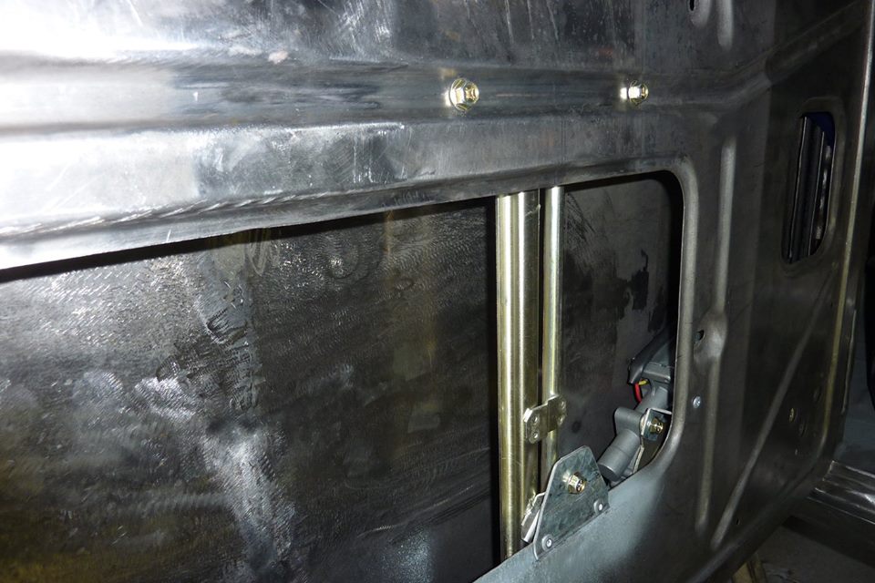
Pushing down on the inside lock rod would push it into the locked position. The pivot link was made as long as I could to get enough travel without binding. Also made sure the pivot link is level halfway through its travel to prevent binding as well. A nyloc nut on the pivot bolt will used for final assembly.


Willys1254.jpg

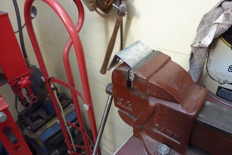
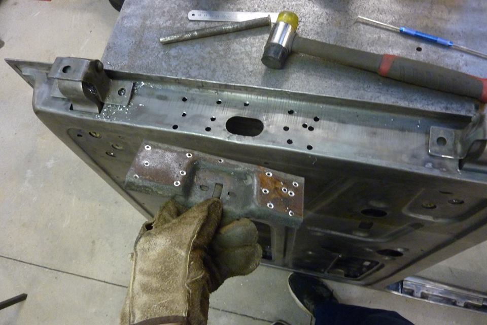
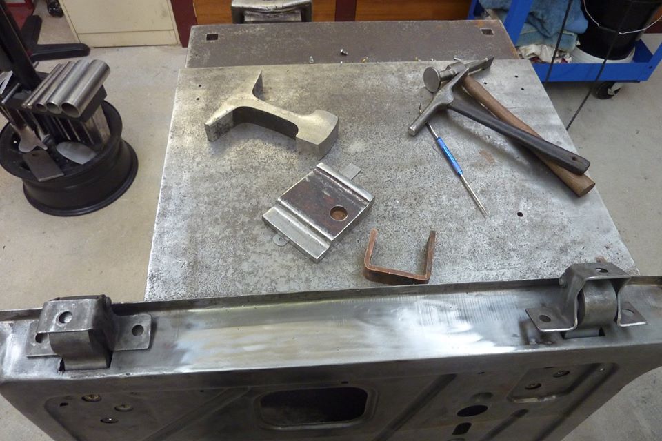
Next thing was to make a mount for the central locking actuator/solenoid. I didn't want another set of screws or rivets at the end of the door, or on the inside either. So will hide them under the door card. The metal was too thick for my folder so knocked it over in my smallest vise.


Willys1255.jpg

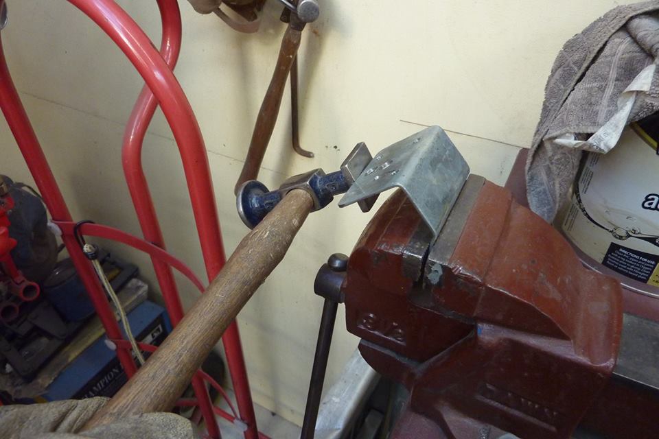
Needed a joggle in it to suit the door. So after the first fold was made, I raised it up 1/4" and then bent it back the other way. Held this hammer against the edge to start with and hit it with a nylon mallet.
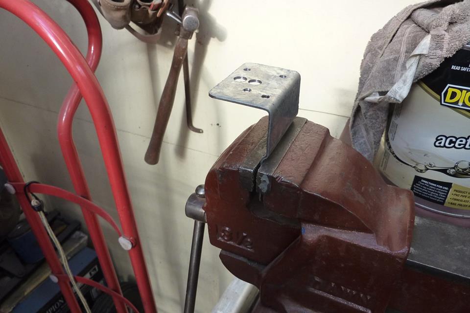
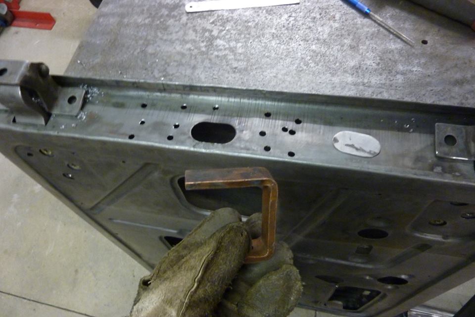

Willys1256.jpg

One joggle!


Willys1257.jpg

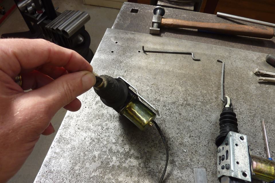
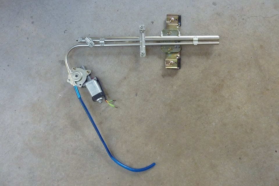
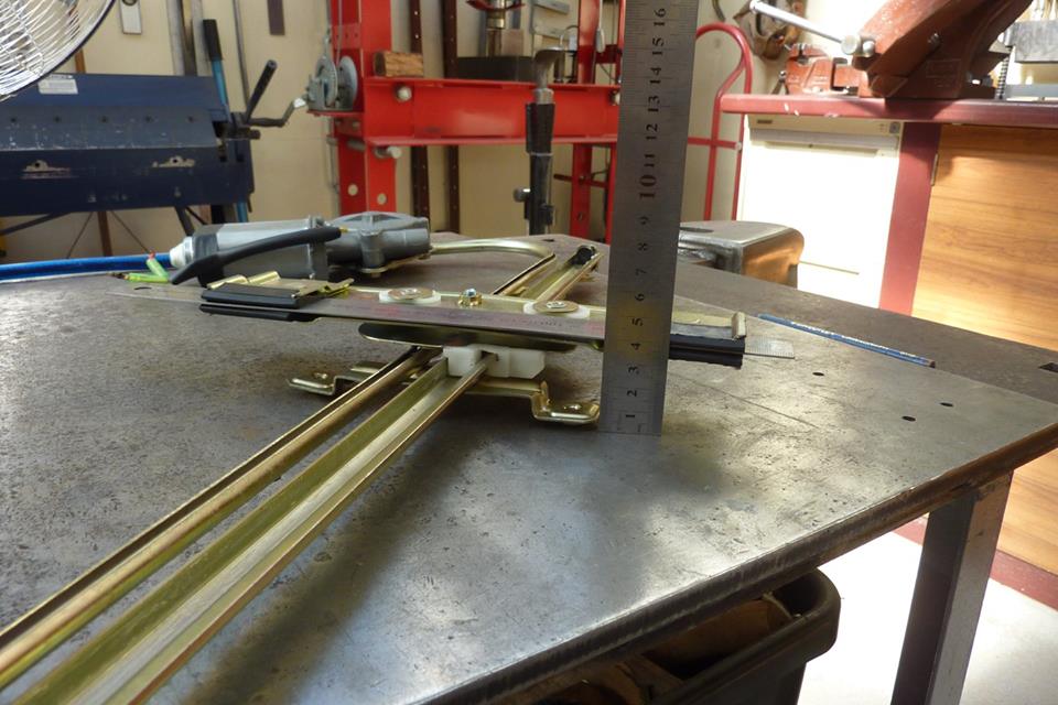
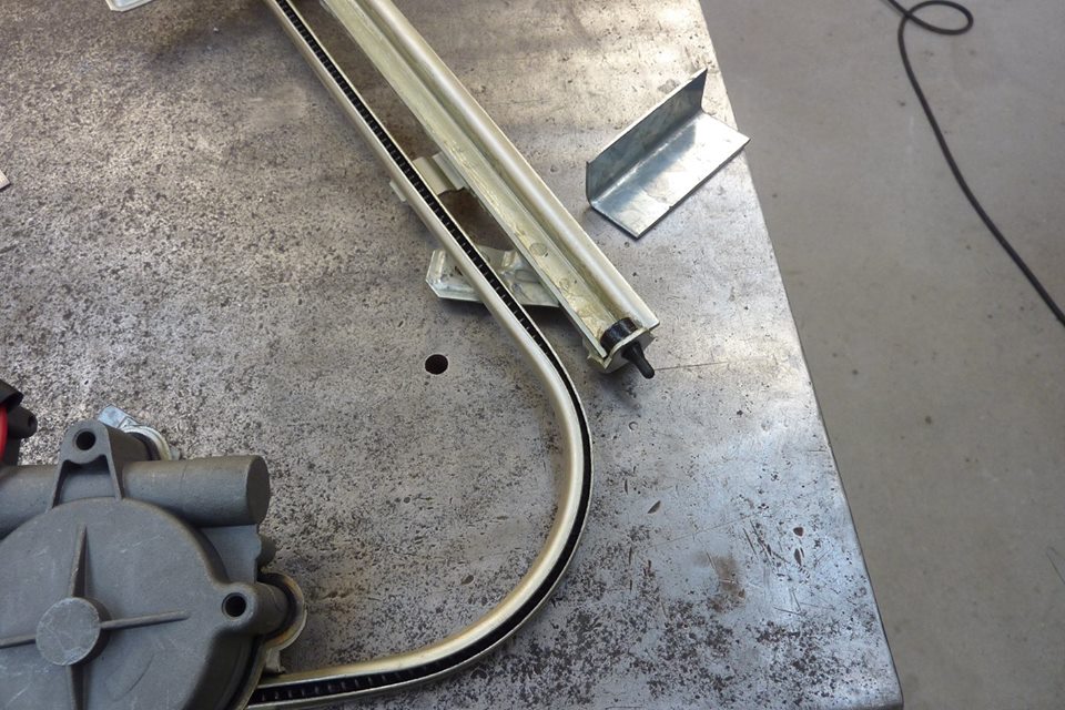
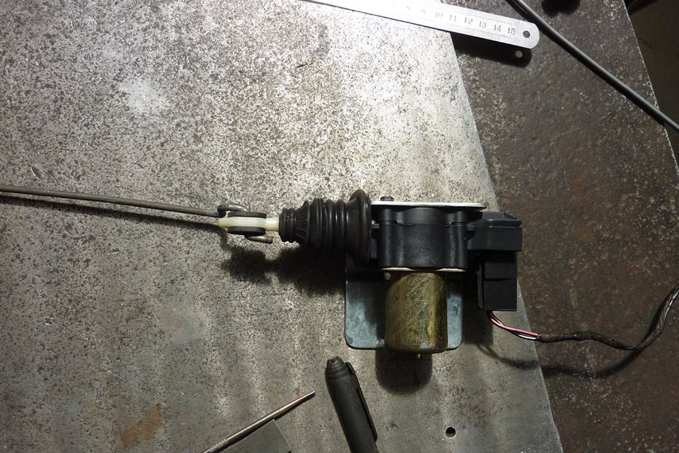
It clears the motor nicely. These came out of a XJ Jeep Cherokee, pre 97, but are the same found on many GM cars from the 80's and early 90's. They actually have a rack and pinion system in them. Better than the cheap Chinese versions in the kits.


Willys1258.jpg

The stock rod for the actuator won't work as angle is too great and in the way of the end of the glass channel.


Willys1259.jpg

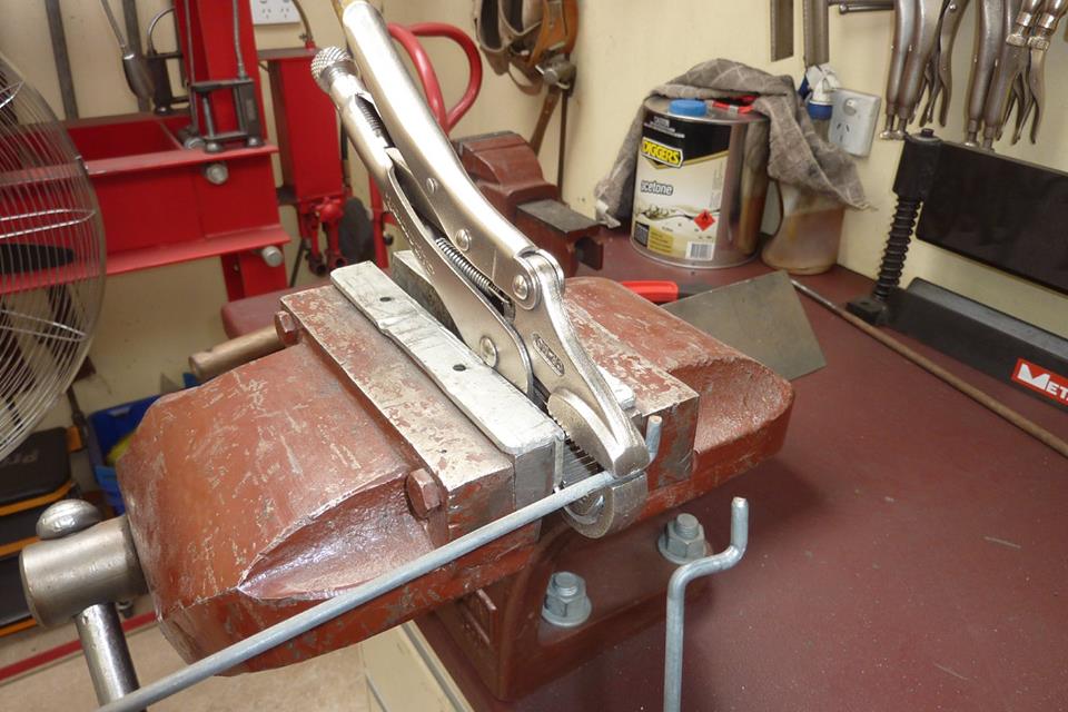
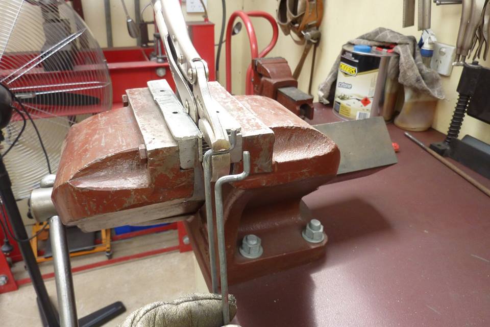
Bent the first bend in the vise but the second bend won't work in it. So clamped a set of Visegrips in the vise to make the second bend.


Willys1260.jpg

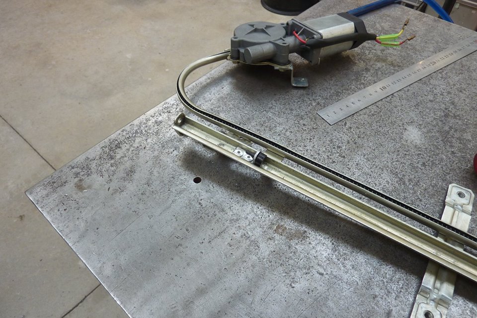
Knocked it over and now matches the stock rod.


Willys1261.jpg

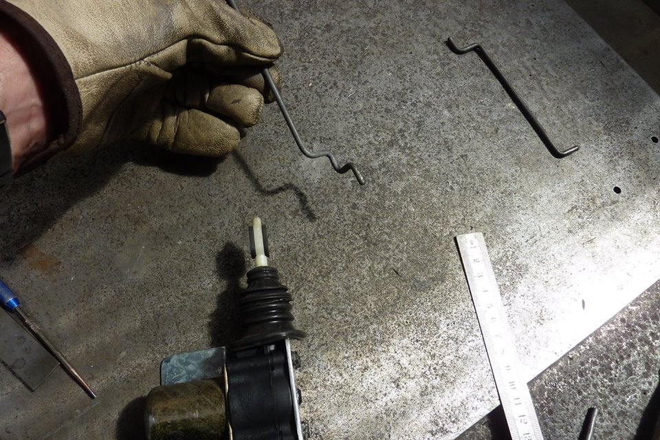
I also put another step in it so it would line up directly under the pivot link. Less wear on the actuator this way.


Willys1262.jpg

First two bends are to locate it in the top of the actuator.


Willys1263.jpg

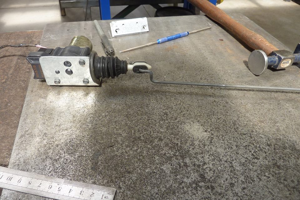
Last two bends are to get it lined under the pivot link.


Willys1264.jpg

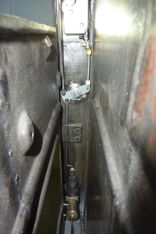
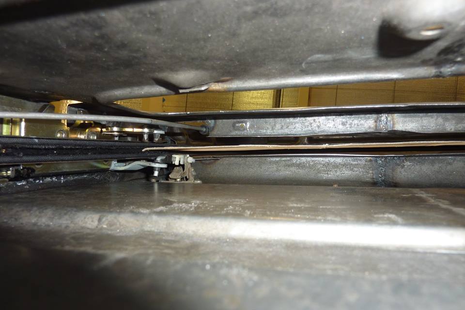
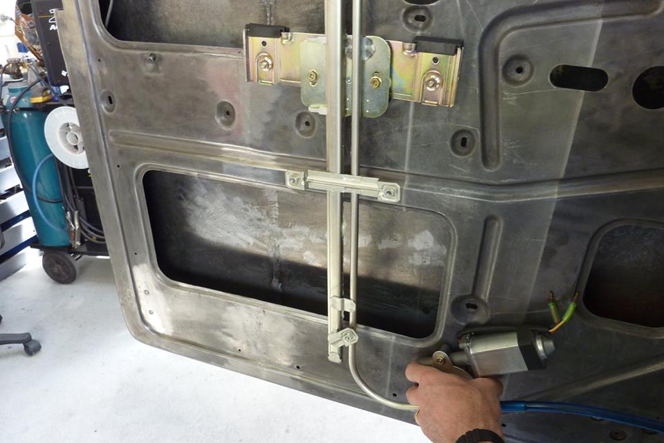
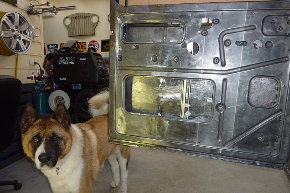
Here it is all mounted up. In the locked position now.
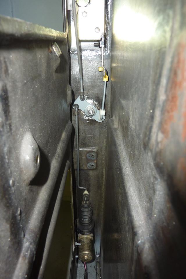

Willys1265.jpg

Unlocked position.


Willys1266.jpg

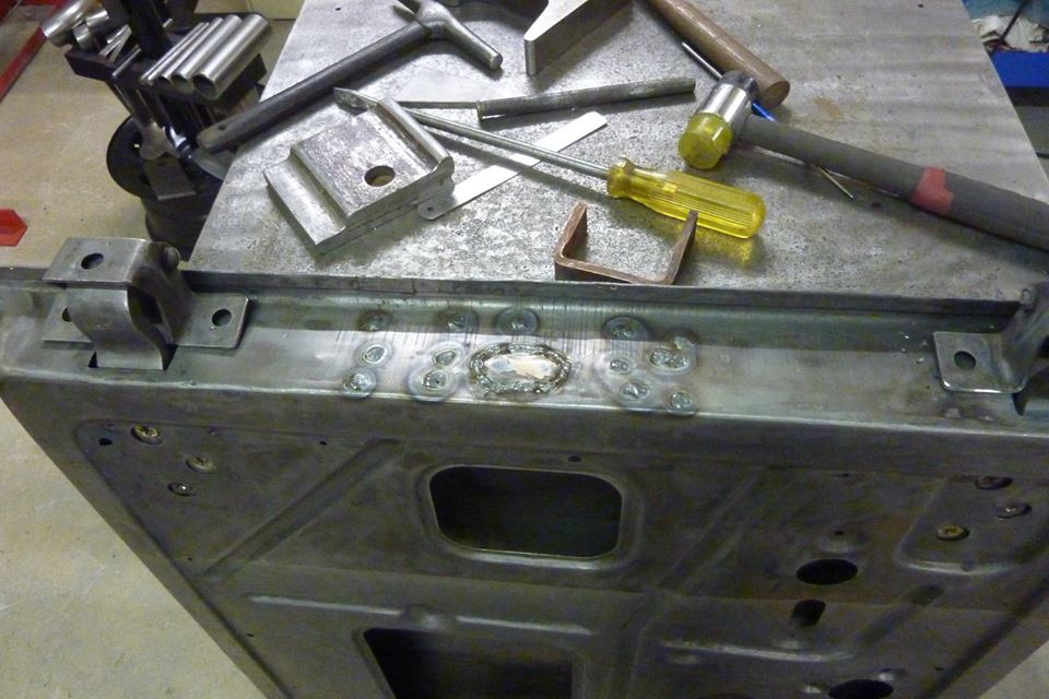
Screws will be hidden under the door card which sits inside the recess. Wafer head self drilling screws were used to hold it in place. The self drilling ones are hardened and won't wallow out over time. Can also see why the joggle was needed in the bracket.
I haven't checked in on your project for a awhile. It would appear that the great work is still flowing from your superior craftsman hands.

Sent from my SM-T230NU using Tapatalk
 
Marcus,

Amazing work per usual.

Just out of curiousity, how do you plan and track your projects? Sketches? Spreadsheets? Engineering drawings? All in your head? And how do you note changes to the plan and/or design?

The combo of vision, action, and detail is very impressive.

Cheers!


Scramboleer
 
I haven't checked in on your project for a awhile. It would appear that the great work is still flowing from your superior craftsman hands.

Sent from my SM-T230NU using Tapatalk

Many thanks Dan.

Marcus,

Amazing work per usual.

Just out of curiousity, how do you plan and track your projects? Sketches? Spreadsheets? Engineering drawings? All in your head? And how do you note changes to the plan and/or design?

The combo of vision, action, and detail is very impressive.

Cheers!


Scramboleer

90% of it is in my head and just go about bringing it into reality. Plan hasn't really changed since I started. Some things like the locks and handles I had originally planned to use the donor ones, but they simply didn't fit. So set about the best way to do it instead. Prefer always to use Jeep/Willys stuff if I can, but only if it suit and functions correctly.
 
Once again I like you approach to tackling problems. I haven't been able to figure out how to make my bear claw's lock. Now that I've seen your pivot and cross over ideas I need to take another look at mine to see if I can apply your idea to make mine work. Thx.
 
Once again I like you approach to tackling problems. I haven't been able to figure out how to make my bear claw's lock. Now that I've seen your pivot and cross over ideas I need to take another look at mine to see if I can apply your idea to make mine work. Thx.

Hope it works for you too.
I was most worried about getting the locking working as couldn't find how anyone else had done it using the universal bearclaws. Was relieved that it worked out.
 
I hope you realize how important what you are doing for others is. It is literally a pleasure to watch you solve your problems that arise. I personally appreciate this log and will be poaching some ideas for sure.
 
Little by little I'm getting there.


Willys1267.jpg

I am getting rid of the 1/4 vent windows and going to one piece glass. It means that the door check bracket has to be removed as can't run that style anymore. I'll have to come up with something else like a simple strap that the CJ Jeeps have.


Willys1268.jpg

To fill all the spot weld holes I just use a thick piece of copper under the hole and weld it shut with the mig. The oval hole I have cut a patch for.


Willys1269.jpg

All the holes gone. Will grind them down to a razor blade thickness above the parent metal. Then flap disc to flush followed by a strip disc.


Willys1270.jpg

Hammer dollied the weld area flat and all done.


Willys1271.jpg

Out of the four doors I had, only one of the window channels needs replacing. I'll be using the same channels that ran down the latch end of the doors at both ends now. They are left and right so need one of each in each door.


Willys1272.jpg

Fortunately I only had to fold up the channel and the mounts were still alright.


Willys1273.jpg

The channel will sit inside the door where shown by the holes drilled. It will sit at the same height as the latch end of the door. Also note that 5mm-3/16" spacer was added to the mounts to space it out to line up under the window frame correctly and not interfere with the hinge reinforcements.


Willys1274.jpg

Just showing on a scrap door the curved piece in the corner, as well as the piece holding the inner and outsides together, that has to be removed.


Willys1275.jpg

The latch end of the door channel alignment was first checked to make sure it was a straight line from the window frame down all the way inside the door channel. Used the old 1/4 vent channel inside the other one to check, but also found a string line worked well. Glass does not bend so needs to be inline. The factory holes were a bit off so I welded them shut and moved them over and then copied that over to the hinge side of the door.


Willys1276.jpg

I bought two 2400mm-96" lengths of flexible window channel the same as stock. They are cloth covered with the bristles on the sides.


Willys1277.jpg

Can see the back of the channel is segmented allowing you to bend it around the corners.


Willys1278.jpg

The channel inside is made from aluminium.


Willys1279.jpg

Can see how it will come up out of the new position at the front of the door.


Willys1280.jpg

To help it bend around the corners I found a carpenter's pencil worked well. I secured the channel the same as stock with some small counter sink screws.


Willys1281.jpg

I cut some cardboard roughly into shape and then marked around the inside edge of the window channel. The added the depth of the channel, 10mm-3/8", to that mark with some dividers.


Willys1282.jpg

Can see how it sits inside the channel. I made it go inside the door to add some stability to the front edge when down.


Willys1283.jpg

The bottom of the template is level with the top of the door card recess.


Willys1284.jpg

I was happy to see that it cleared the door handle linkages. I will make templates from MDF next using the cardboard one to scribe around.
 
Awesome! Because I want to see it so bad, what is your ETA on getting the cab on the frame?

I'm trying to do as much as possible to the cab first before it goes on the chassis as takes up a lot of room and makes it harder to work around it. Wont be until next year as there we be a lot of work in the front clip!
 
Hi Marcus, did you see if it would be possible to reverse the door check bracket, as in, instead of the flat rod going into the door as you close the door, it goes into the area in front of door. Markrh.
 
Hi Marcus, did you see if it would be possible to reverse the door check bracket, as in, instead of the flat rod going into the door as you close the door, it goes into the area in front of door. Markrh.

I haven't looked into that to see if the A pillar is deep enough to take it. Would be a neat solution though so will check it out. :)
 
Willys1285.jpg

Bought a universal electric window kit. I went with the motor off around the side rather than fitted directly to the bottom of the guide rail to give me more mounting options.


Willys1286.jpg

Before committing to cutting out my final window template, I wanted to make sure it went into the door deep enough. You need a minimum of 38mm-1.5" below the window sill to make sure it won't foul when the window is fully up. I made it 50mm-2" to give me a bit of room.


Willys1287.jpg

I thought the best place in height would be that the mounting bracket would sit directly over the ridge on the inner panel. Would be more strength there and the bolts heads would sit inside the ridge making them near flush so the door card would not bulge over them.


Willys1287a.jpg

Still enough room for the motor to be off the bottom of the door. The motor is normally faced toward the hinges.


Willys1288.jpg

Transferring the cardboard template over to some MDF bracing board that was 5mm-3/16" thick. I choose this thickness as was the same as the stock glass that was in there. Can also see the 1/2" I added extra to the bottom. Also made sure the front and back edges were square to each other.


Willys1288a.jpg

The best place to centre the guide rail of the electric window system is at the balance point. This would be the middle if top and bottom, plus both sides were parallel to each other, but not the case with one piece windows. So I found the point by balancing it over a round pencil and marked the spot. Primitive but effective.


Willys1289.jpg

No trimming was needed and fitted first go. The balance point of the template was marked from top to bottom so I could workout where the the electric window needed to be fitted.


Willys1289a.jpg

No binding as it went down either. I could also mark the door where the balance line was at different points. It must remain exactly parallel to the window channels on each side though.


Willys1290.jpg

To know what the distance from the mount to the glass needed to be, I measured from inside the panel to the side of the template close to where the bolts would go. Did the same for the bottom mount.


Willys1291.jpg

This is flipped around to show how much needs to be trimmed off the top to fit inside the door and have the mount on the ridge. Balance point line on the template tells me where to mount the guide rail left to right inside the door. I had it lined up exactly in the middle of the left and right glass clamps.


Willys1292.jpg

The ruler inside the clamps for the glass gives me where to measure too from the inside panel to the glass. It measured 38mm and I only needed 32mm. So I flatted the mounting bracket enough to loose the 6mm extra.


Willys1293.jpg

The two mounting bolts are now holding it in place. I made sure the guide rail was parallel to the window channel to stop any binding. Also put a straight edge across the template to make sure it stayed flat as it went up and down to check the mounting position was right depth wise. Our American Akita doing a photo bomb!


Willys1294.jpg

The bottom mount had to be flatten some as well as wanted it to sit back a bit from the panel face. You can make out the bolt I will use also to support the motor itself.


Willys1295.jpg

A simple bracket with a little joggle in it secures the bottom of the guide rail. Made up a Z bracket for the motor to keep it supported and off the door skins. Could have also bolted with a spacer directly through the inner panel, but didn't want the thick bolt head to stick out.
 
Last edited:
Willys1285.jpg

Bought a universal electric window kit. I went with the motor off around the side rather than fitted directly to the bottom of the guide rail to give me more mounting options.


Willys1286.jpg

Before committing to cutting out my final window template, I wanted to make sure it went into the door deep enough. You need a minimum of 38mm-1.5" below the window sill to make sure it won't foul when the window is fully up. I made it 50mm-2" to give me a bit of room.


Willys1287.jpg

I thought the best place in height would be that the mounting bracket would sit directly over the ridge on the inner panel. Would be more strength there and the bolts heads would sit inside the ridge making them near flush so the door card would not bulge over them.


Willys1287a.jpg

Still enough room for the motor to be off the bottom of the door. The motor is normally faced toward the hinges.


Willys1288.jpg

Transferring the cardboard template over to some MDF bracing board that was 5mm-3/16" thick. I choose this thickness as was the same as the stock glass that was in there. Can also see the 1/2" I added extra to the bottom. Also made sure the front and back edges were square to each other.


Willys1288a.jpg

The best place to centre the guide rail of the electric window system is at the balance point. This would be the middle if top and bottom, plus both sides were parallel to each other, but not the case with one piece windows. So I found the point by balancing it over a round pencil and marked the spot. Primitive but effective.


Willys1289.jpg

No trimming was needed and fitted first go. The balance point of the template was marked from top to bottom so I could workout where the the electric window needed to be fitted.


Willys1289a.jpg

No binding as it went down either. I could also mark the door where the balance line was at different points. It must remain exactly parallel to the window channels on each side though.


Willys1290.jpg

To know what the distance from the mount to the glass needed to be, I measured from inside the panel to the side of the template close to where the bolts would go. Did the same for the bottom mount.


Willys1291.jpg

This is flipped around to show how much needs to be trimmed off the top to fit inside the door and have the mount on the ridge. Balance point line on the template tells me where to mount the guide rail left to right inside the door. I had it lined up exactly in the middle of the left and right glass clamps.


Willys1292.jpg

The ruler inside the clamps for the glass gives me where to measure too from the inside panel to the glass. It measured 38mm and I only needed 32mm. So I flatted the mounting bracket enough to loose the 6mm extra.


Willys1293.jpg

The two mounting bolts are now holding it in place. I made sure the guide rail was parallel to the window channel to stop any binding. Also put a straight edge across the template to make sure it stayed flat as it went up and down to check the mounting position was right depth wise. Our American Akita doing a photo bomb!


Willys1294.jpg

The bottom mount had to be flatten some as well as wanted it to sit back a bit from the panel face. You can make out the bolt I will use also to support the motor itself.


Willys1295.jpg

A simple bracket with a little joggle in it secures the bottom of the guide rail. Made up a Z bracket for the motor to keep it supported and off the door skins. Could have also bolted with a spacer directly through the inner panel, but didn't want the thick bolt head to stick out.

Impressive!


Sent from my iPhone using Tapatalk
 
Willys1296.jpg

I wanted the window to stop when the top edge was flush with the window sill. The one at the bottom of the track/rail was too low.


Willys1297.jpg

Before removing it I marked where I wanted it to stop plus a few millimetres for the rubber stop compression. I prefer this way than the common bolt as wont damage the nylon guide and is not harsh when it reaches it.


Willys1298.jpg

Next up is the window felt that goes on the window sill for the outside of the glass. Most I see just run it straight into the corners, but thought I would try and bend it to suit the radius instead.


Willys1299.jpg

Just using things I had in the washer draw, I made up this little jig. The felt is the same as used in the window channel and is attached to cloth that is clamped into a steel backing with wire rod inside the edges.


Willys1300.jpg

Just drew the window sill outline onto the cardboard template I had used for the window.


Willys1301.jpg

Was a bit fiddly passing it through back and forth and also had to keep straightening the rest of it. Make sure the wire can come out the end as it needs to go somewhere as you shrink the inside radius.


Willys1302.jpg

I got most the the second bend done as well before cutting it with a little extra spare.


Willys1303.jpg

Just about there now and will cut it with tin snips after marking it on the angle it needs.


Willys1304.jpg

Can see how it follows the radius around.


Willys1305.jpg

If I had just gone straight ahead you would see it disappear leaving a gap looking from the outside.


Willys1306.jpg

I used 1/8" rivets to hold it in place. I want all the holes in place before it gets painted so why I have already installed it, even though it has to be removed again.


Willys1307.jpg

A pillar corner from the outside.


Willys1308.jpg

Same material for the guide the whole way around now. I found it also supported and guided the glass better on the front edge as it was going up than before.
 
Nicely done as usual, Marcus. Hopefully it won't be too long and I will refer back to this info.
 
Hi Marcus. Fantastic, Amazing work! Your Knowledge and Talent on all this is Stellar!! Is there Anything that You CAN'T Do?? Great Work Man!! Pivnic
 
Back
Top