GrandWillys Project

The surfaces with be zinc coated first and then seam sealer added near the edge and fold. I will then use my spot welder to fix it the same as factory.
 
have you tested spot welding zinc coated surfaces? I would think it would give you a spark shower. I only have experience spot welding clean and slightly contaminated metal. Any contamination caused blowouts and spark showers. No good! Great idea to coat it in zink though if it works.
 
I work at a sheet metal fab company and yes, when you spot weld zinc (galvanized actually) you do get a shower of sparks. I'm not sure how that would cause a contamination though.
 
Yep, get the sparks but still works well. One technique is to give a quick squeeze to burn the paint just under the contacts and then a longer one for the weld itself.
 
Willys1104.jpg

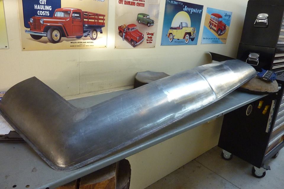
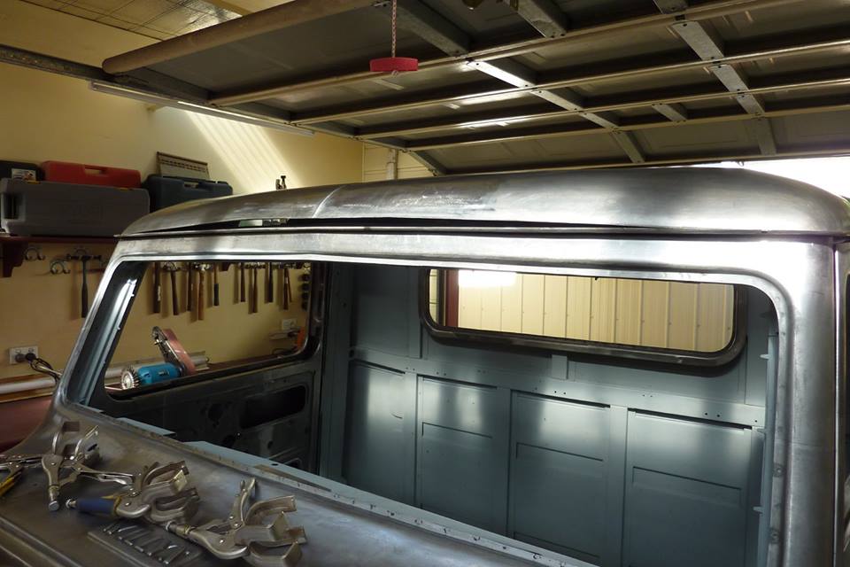
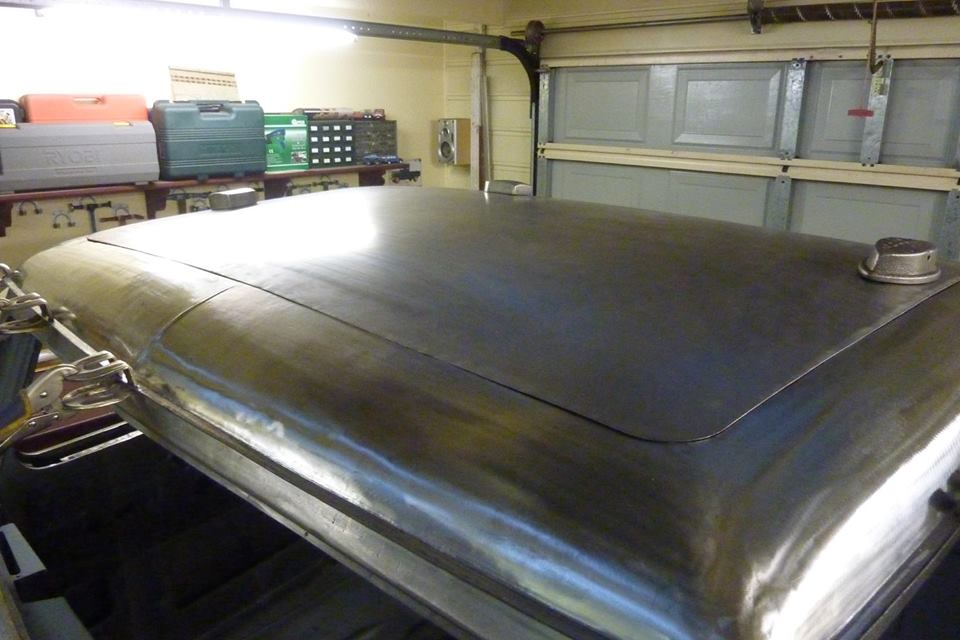
Welded the three pieces that make up the front together and was quite happy with the look.


Willys1105.jpg

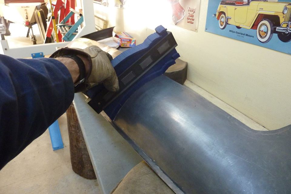
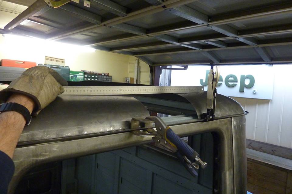
As always, I checked the profile at the same points on each side to make sure it was even.


Willys1106.jpg

Well it is nowhere near the same this time!


Willys1107.jpg

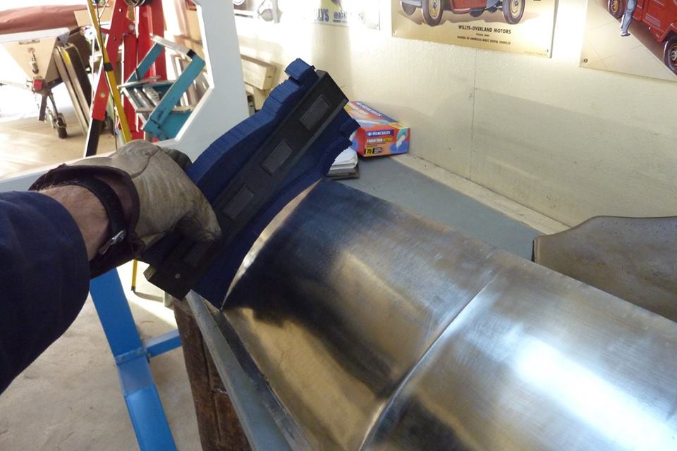
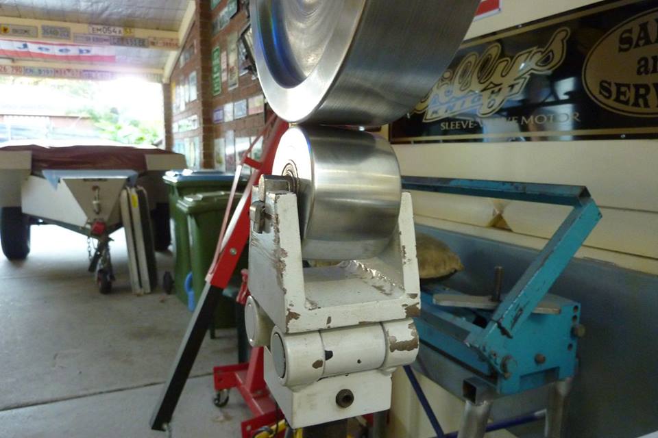
I wheeled it to match the other side using a rubber band on the upper wheel to make it go quicker. Looked good matching many points left to right.


Willys1108.jpg

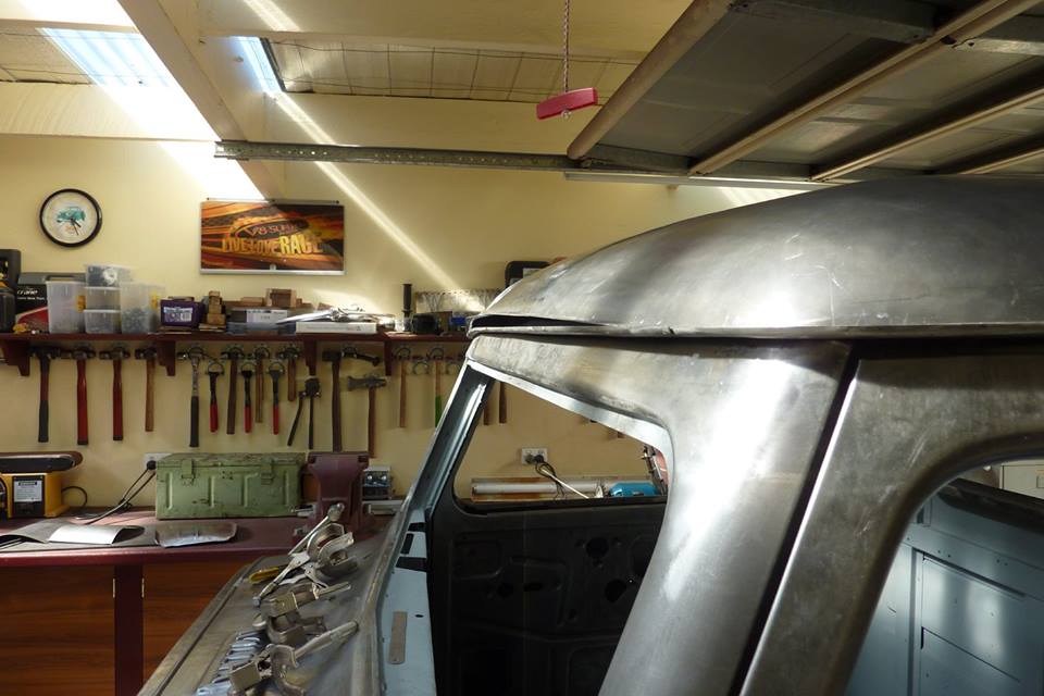
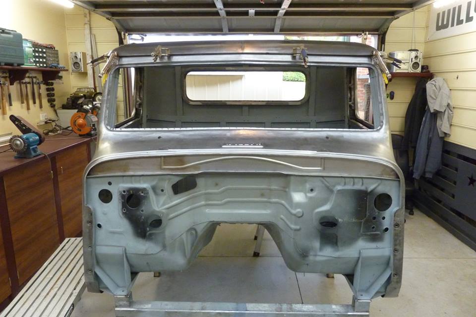
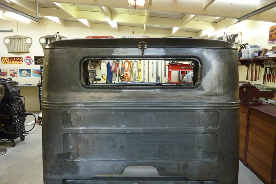
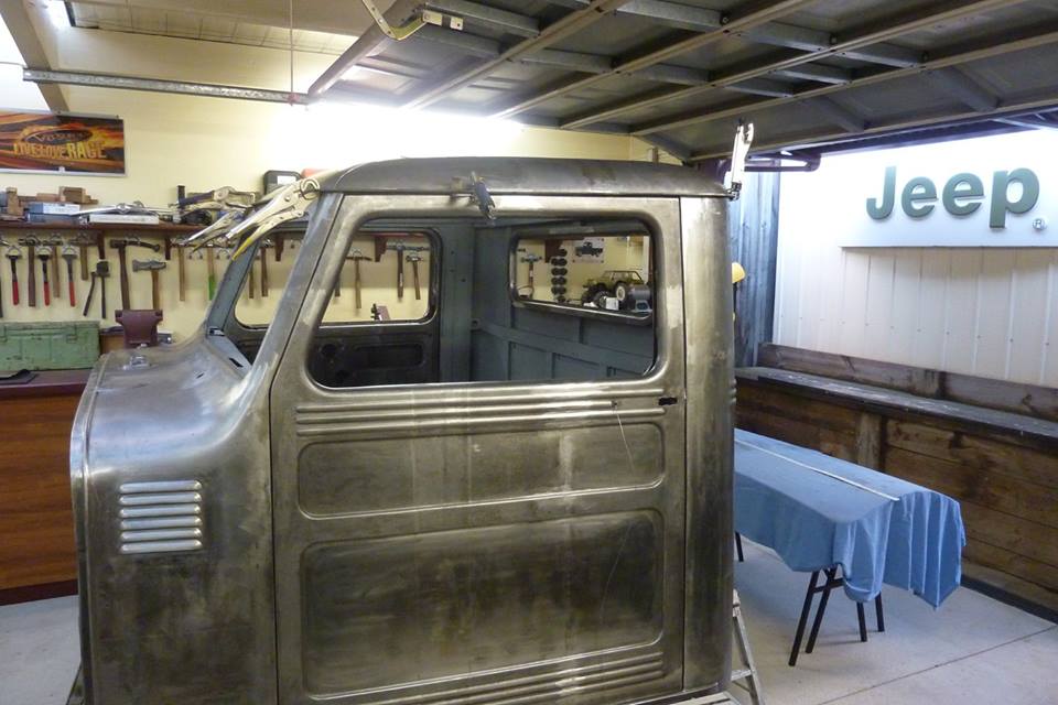
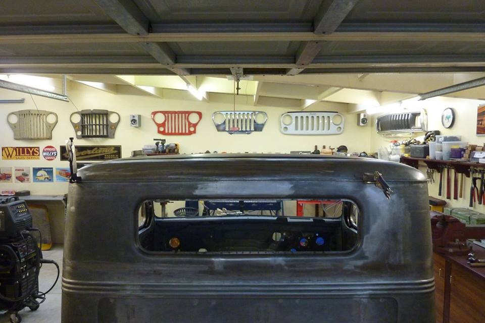
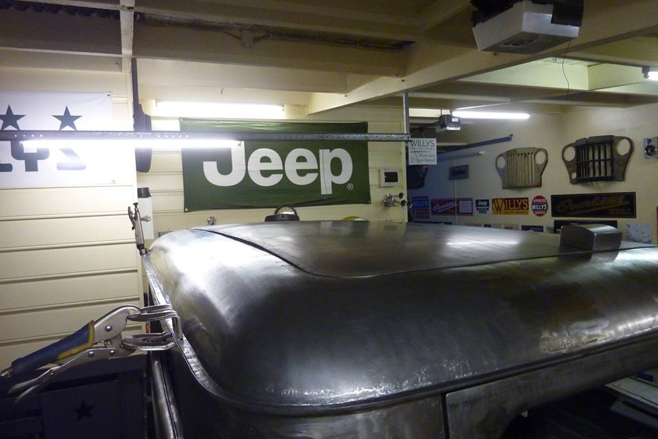
But all was not well when I placed it back on the cab to check fitment!


Willys1109.jpg

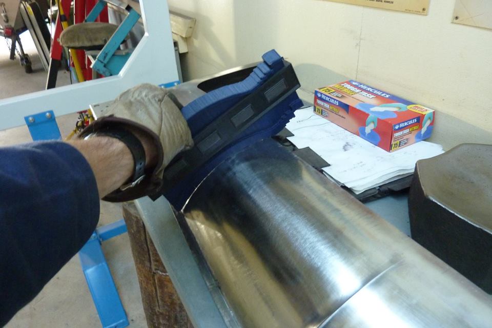
Not sure if it was because I used the rubber band when wheeling as it only bends rather than stretching to change shape?


Willys1110.jpg

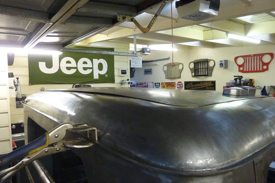
Sits up a lot as should only have a slight rise. Tried wheeling more without the rubber but was having some trouble on my own with it this long and keeping it level when running it through.


Willys1111.jpg

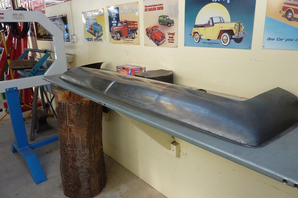
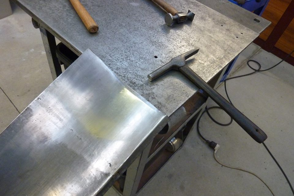
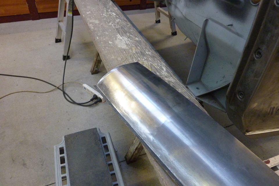
Cut it right in half down the middle of my nice centre crease. :( Even in half you can see how much curve it has. To my mind it needs to be stretched along the bottom to pull it down.


Willys1112.jpg

I hadn't been able to wheel right up to the flange as the centre of the lower anvil/wheel is away from it. So tilted the lower so I could get up to the edge to stretch that area to see if that would help.


Willys1113.jpg

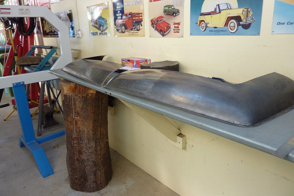
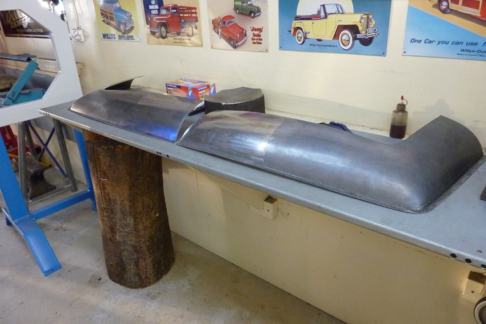
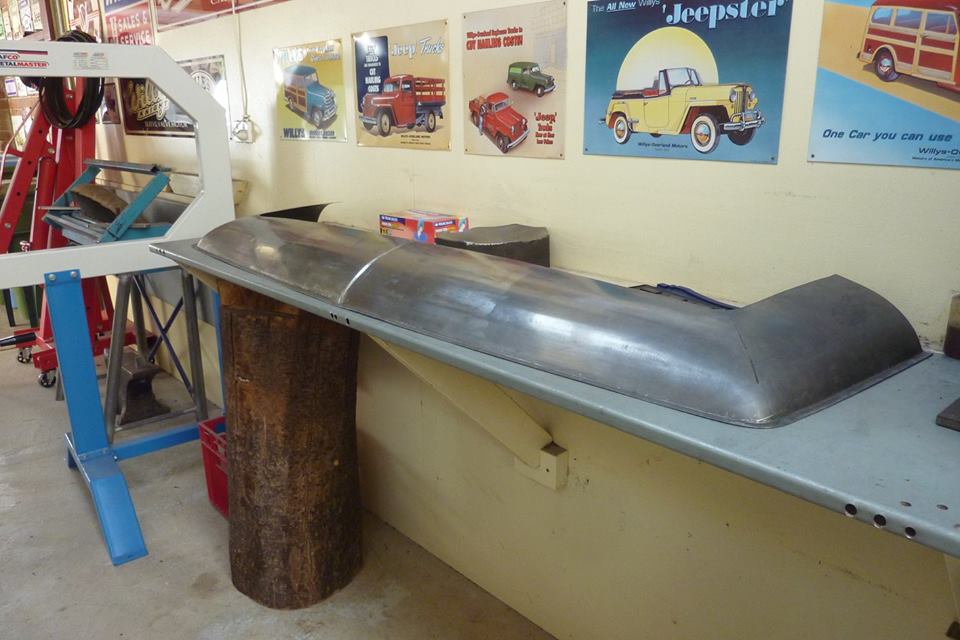
I did some hammering along the edge over the welding bench as well and it is getting the desired result. The left one in the picture is the one worked.


Willys1114.jpg

Placed it also over an original roof panel to see the difference. I have left out the more vertical section at the gutter line as think at the front the softer slope looks better.


Willys1115.jpg

Was not sure what I would do with my crease as it was completely wheeled out and would fit in my bead roller anymore either. I didn't want to cut off the overlap, weld it, and then stretch it once again to put the crease back by hand. So just put the shape back in by hand over the edge of the bench while still in two halves.


Willys1116.jpg

Got the shape back and did the other side as well which had to match exactly.


Willys1117.jpg

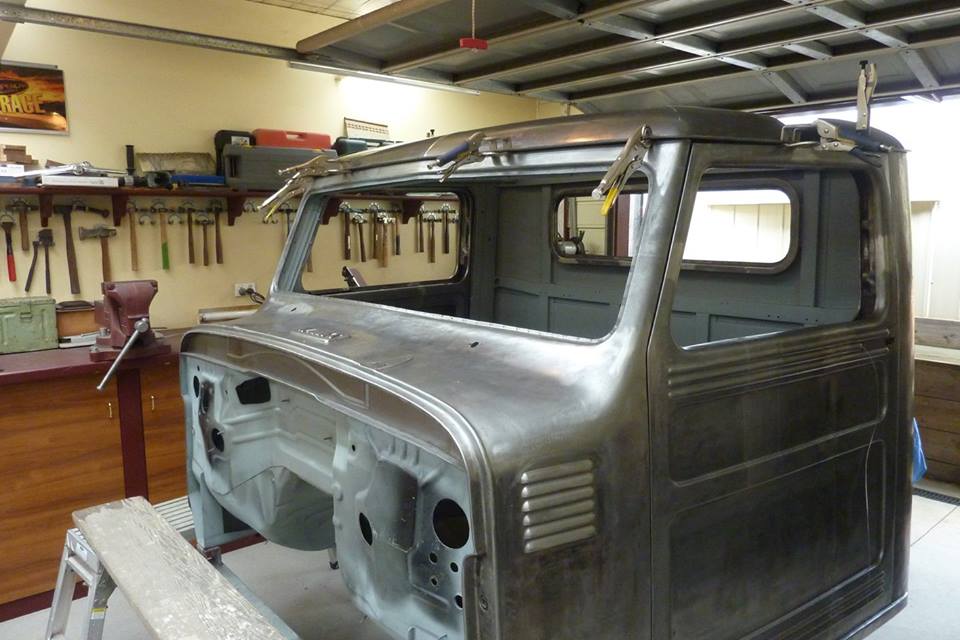
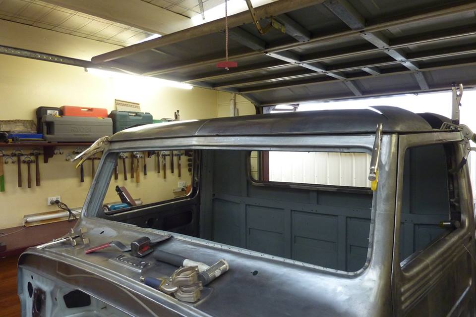
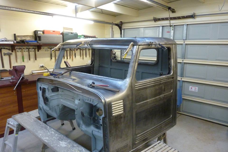
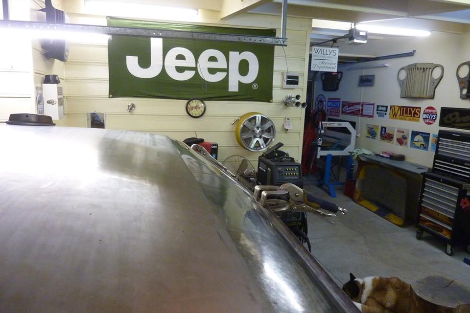
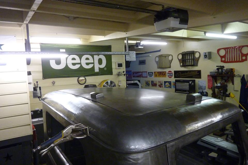
So welded it together again while clamped down to the gutter and then took it off to planish the panel.


Willys1118.jpg

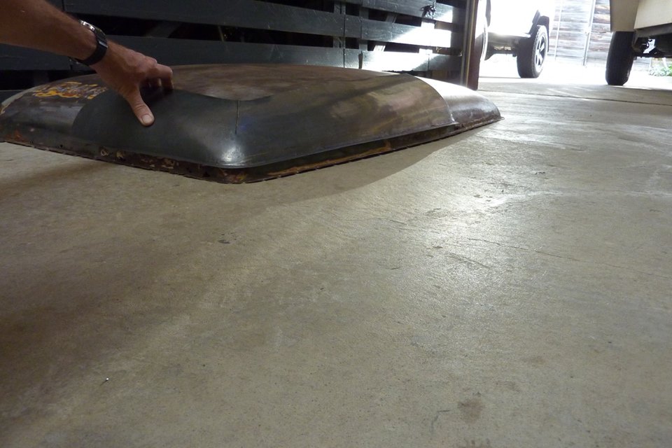
So the height is one inch shorter across the front and a softer curve to it.


Willys1119.jpg

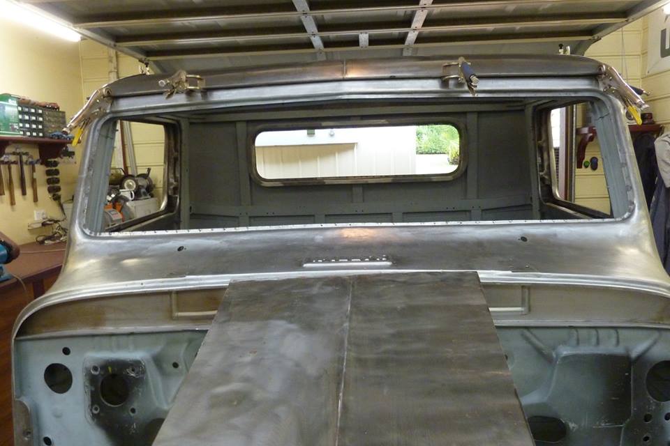
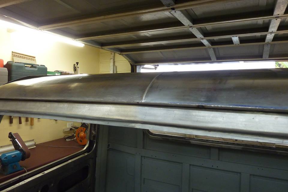
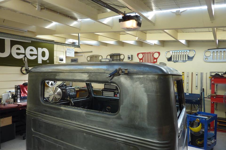
Here is a scrap piece of bonnet with its centre crease to get an idea of how it will look together.


Willys1120.jpg

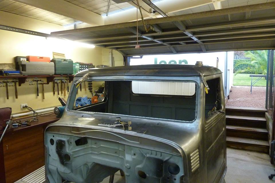
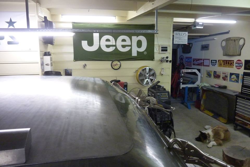
I also wheeled a bit more crown into the rear as thought it was a little too flat and now matches the front as well. Still 1.5" less than stock in height overall at the sides and 2" lower in the middle.
 
Last edited:
Looks really, really sharp! Can't wait to see the profile with the front end on. Have you done a rendering of what the finished profile should look like and what changes if any will there be to the front fenders and hood? Great work as always.
 
Marcus
Incredible as always.
I would sure like to see a tutorial video of you planishing some weld down I understand the basic concept but my hammer dosent agree. ( stupid hammer)

Sent from my SM-T230NU using Tapatalk
 
Unfortunately Dan plashing a weld just comes from feel after doing it a lot. In the beginning I over did it as was use to hammering much thicker steel. Biggest thing is to make the weld an even thickness while welding and after grinding, but still slightly more than flush, and hammer as evenly as possible in spacing and force as you go along. Any areas that had thicker weld will need more and where you come to a corner. Which is why it is better to round them. If it is a mig weld I make sure the weld turns blue while grinding so it softens the weld making it easier to stretch and less prone to cracking. Won't see that written anywhere as people jump down your throat and think you are a crackpot! But it works for me as must be annealing it and why I thought about doing it that way.
 
Thanks for the comment Brian.
I have never done a rendering but played with photos a bit to see if the proportions I was seeing in my head worked somewhat. They are right at the beginning of this thread somewhere.

Post number 9. http://www.oldwillysforum.com/forum/showthread.php?1041-Grand-Willys-Project

Sorry that I can't quote anymore but then my spacebar doesn't work as I type! This is the only forum it happens on????
 
Thank you for the info. I love watching a guy who excels at what he does. It's like everything. Lots of practise.

Sent from my SM-T230NU using Tapatalk
 
Willys1121.jpg

Did some more work on the front piece and can see how much it has come down. Sitting pretty flat now when before it was 30mm-1 3/16" up in the middle.


Willys1122.jpg

Just drops into the gutter now.


Willys1123.jpg

Close up of the centre bead I hammered in by hand.


Willys1124.jpg

Now to join the front and sides. Need to stretch and reduce the radius slightly at the ends to raise it so it doesn't dip in the middle.


Willys1125.jpg

Still has the wedge shape to it even after I have reduced the front by 25mm-1" and the rear by 40mm-1.5".


Willys1126.jpg

Just need to weld the front corners up and do the final shaping and planishing before the centre goes on.
Not sure if to fully spot weld the perimeter on before welding the centre infill panel in, or just heavily clamp it and weld it there so it can be taken down to dress the welds afterwards? Don't want it to change shape at all where it fits into the gutter after all this work is my main concern.
 
Last edited:
With all the shape in the corners, I doubt the center panel will be able to move the alignment the any, even if it wasn't heavily clamped. That said, clamping it wouldn't hurt. .. and it's a very goodd idea to keep that panel removable until it's done. That way you can pop it in the English wheel if you need to... and planishing is easier because access is easier.
 
I really do like the flattened roof. I wasn't sure when I was looking at your original photoshop renderings, but I am sold for sure. Let us know what magazines this truck is in when you're done!
 
Willys1127.jpg

Woo hoo. First time to see what it looks like with the infill panel that was wheeled up at the metal meet 18 months ago. Fits way better than expected! Thanks again to Nigel being at the other end of the sheet while wheeling it all day and the guidance of Peter Tommasini.


Willys1128.jpg

I like the look across the back as well.


Willys1129.jpg

Will have to reshape along here to get it to fit a bit better.


Willys1130.jpg

Along the front it is looking quite good. Just in the middle though you might be able to see that it dips down. I will put more curve in the front piece to make it blend.


Willys1131.jpg

Flows a lot better now. Did it all by hand with a dolly with more crown and a flat faced hammer and a flipper.


Willys1132.jpg

The back is looking like it is nearly there as well.


Willys1133.jpg

Just the weight of a dolly gets the roof panel to sit down and a single finger pressure can lift it from underneath.


Willys1134.jpg

Shaping up to be alright.


Willys1135.jpg

Think I am ready to scribe around the edge to cut the overlap off ready for a butt join.


Willys1136.jpg

I have come up with this to support the infill panel once the perimeter roof is cut to size so it doesn't just fall through!


Willys1137.jpg

I measured the difference between the stock and this new roof and it is 38mm-1.5" lower overall. It has taken the baseball cap look out of it.
 
Last edited:
Love the way it all looks. Can't wait to see it wearing paint. Really love the lines.

Sent from my SM-G920V using Tapatalk
 
Your metal fabrication skills are amazing! I would love to be able to do that.

I'm really curious how you keep your metal from rusting while you are building your truck?? After a couple of days I have to deal with surface rust.
 
Back
Top